[Today’s run: 2 miles with the dog]
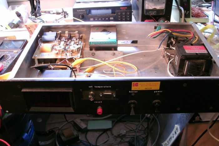
Here’s a picture of my 10 Mhz GPSDO in it’s current state. (GPSDO : GPS disciplined oscillator, a form of 10Mhz frequency standard)
I picked up this enclosure at a CSU Suplus auction a long time ago in Ft. Collins. It is some kind of heater control and has a Kodak sticker on it. It has +/- 12 VDC and 5 VDC power supplies already in it. I’m going to use the +/- 12VDC along with my +/- 5VDC regulator board which I just made, to produce stable voltage for the frequency adjustment of the VCO.
The VCO is an HP, the silver box with the green connector mounted in the back of the enclosure. It came from an old HP frequency counter. Also from the old counter we have the power transformer on the right which will produce the +24VDC for the VCO heater circuits and the +12VDC for the controller board and +3 VDC for the GPS.
I have mounted a 9-pin RS-232 port on the front and a BNC connector. The serial connector will be switchable, in one mode it will let me talk to the controller board and in the other mode talk to the GPS.
There is a power switch on the front which I am going to use, and an LED that goes with it. There is also a switch labeled “heater” which I’m not sure if I will use. I think probably not. There is a red push-button switch which I will replace with the dpdt serial port switch.
On the front panel there is also a digital display which I believe is a volt meter. I don’t understand the units, for ~5 volts it shows something like 160. At ~12 volts it shows a number around 350. It seems to work for both plus and minus voltages. It was powered by the internal 5 VDC supply, and I will keep it that way. I plan to use it as a visual display of the VCO frequency voltage, which should swing very little. If I remember to write the numbers down periodically I could use it as an indicator of what the VCO is doing.
I actually completed much of this work last winter, but now I’m at least thinking about it again and I have produced the +/- 5VDC regulator board. I need to think about how to mount the various boards.
