[Today’s run: 6 miles]
For Christmas I received a new book about doing projects with vacuum tubes. That has me thinking about the HBR receiver project which I first looked into about 2 years ago.
At that time I traded a non-working receiver project for some HBR parts. One item was a set of coils.
The HBR receiver guys say that the first part to work on is the BFO (beat frequency oscillator). That is just an oscillator which puts out 83-87 kHz, adjustable with a 50 pf variable capacitor.
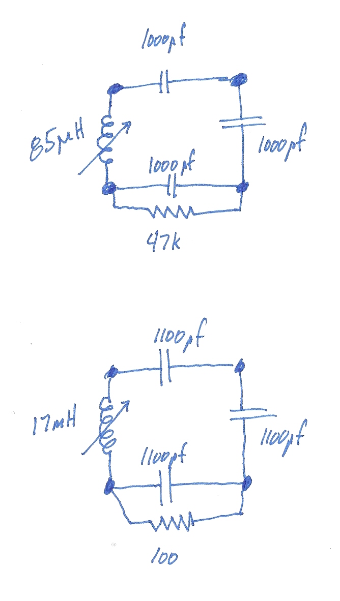
Anyway, I pulled out these coils and two of them are similar. One had a hand-written label “85 kcs BFO”. The other one just said “?”
What’s inside both is actually the same little circuit with a different value for the slug-tuned coil and one resistor. I’m not really sure what this is for. But it doesn’t match what I need. I am contemplating the idea of just using the coil form and building my own coils.
The original HBR plans use a Hartley Oscillator in the BFO. That kind of circuit uses a tapped inductor. I have figured out that my inductor needs to be about 8-9 milliHenries total. I need to wind a few turns on the slug-tuned coil form to see what the mu-factor is. Then I could calculate out how many turns total I think I need. The tap needs to go 1/4th of the way in from the “cold” end.
One problem I have is that I’m not sure if the tapped part should be closer to the slug (on first) or farther from the slug (on last). I’m thinking that if the slug has more effect on the closer windings (the ones put on the form first) then I should put the “hot” end there.
I guess I could tap it in two places, one about 1/4th of the way in and another about 1/4th of the way from the end. Then I could swap which end I’m using by changing the wiring to the pins of the coil.