[Yesterday’s run: 6 miles]
So!
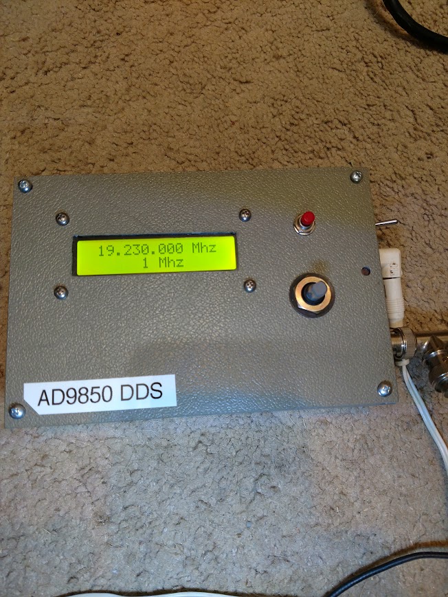
I had built this little box in 2014. It is an Arduino Nano controlling an ebay AD9850 board.
I didn’t like it when I built it, so I put it up on the shelf. I took it down recently to use as a signal source to drive the non-working Belar modulation monitor.
I decided to see if I could find newer software or some other thing which might make the signal source box more useful.
The first problem was that my rotary knob was very funky acting. It clicks, and sometimes it would change a number when it clicked and sometimes not. I found a datasheet for exactly that gizmo. The thing is actually kind of pricey, not one of the cheaper on-line maker-store jobbies. It is an optical encoder but feels like a mechanical one. So I dug into the rotary encoder library for the Arduino. It turns out they divide the “clicks” by 4 in order to deal with switch bounce, I guess in mechanical encoders. If you have 360 transitions per revolution you can do that kind of thing. But mine is optical and something like 32 transitions per rev. So I was turning all day just to get the numbers to change.
They had some code in the library for divide-by-two, which I tried. A great improvement but still not right, particularly if you change directions: after one click toward left it would take three clicks toward right to change a number. I wrote my own one-to-one section and that really relieved the situation. Now when it clicks the number changes. Much better.
Seeing as how I have a pretty good frequency counter which is pretty well matched with my GPSDO frequency source, I next decided to see if I could measure any discrepancy between what the signal source says it is doing and what it is really doing. Long story short: it stunk! It was all over the place. At the top end of the range of this thing (30 MHz) it was off by tens of Hertz).
Some of that is the fault of the little crystal which drives the chip. The thing says 125.0 MHz, but it isn’t. I fooled around with a spreadsheet to try to figure out the real crystal value and I made some progress on that. But it just didn’t seem like it helped as much as I expected it would.
(One of the things one must do with crystal-driven things is let them warm up. So I left the gizmo on overnight. And I left the frequency counter on overnight too.)
I looked at the data sheet for the AD9850. According to the specs, it is supposed to be able to tune small fractions of a Hertz. But the more I played with it, the more I was convinced something was wrong. It was! The Arduino has 32-bit numbers. The math to figure out the frequency “code-word” was doing some division and multiplication with very large numbers. A lot of the significant bits were dropping on the floor. That was why I could change the indication by full-Hertz values and nothing comparable would change in the actual output.
I got started this afternoon on a plan. I’m figuring out by trial and error, with the help of a larger-precision calculator, the correct code-words to make each integer MHz value (1,000,000 Hz; 2,000,000 Hz; etc.) come out of the thing as close as I can get it (and I can usually get it down to a few tenths of a Hz). Then I can add the calculated kHz codeword to the as-figured-out MHz codeword and that should put me within 1 Hz at any place on the dial. I have about half of the 29 values figured out and I’ve proven the concept. I will have to tighten up my 0.0 – 1,000,000 calculation a bit. But already I’m much tighter in the working range 1-13 MHz.