[Today’s run: 3.0 miles with wife and dog]
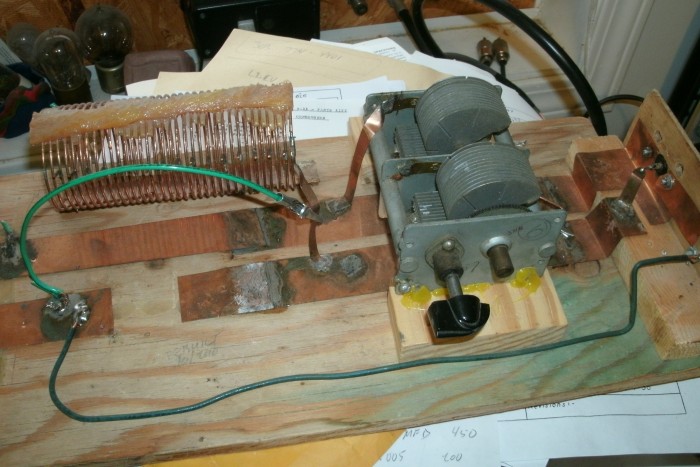
Today’s picture is of my homebrew antenna tuner. The idea of an antenna tuner is to match the impedence of the transmitter/receiver to the impedence of the antenna at the frequency of operation. A match is desirable because it will allow more energy at the right frequency to get out through the antenna.
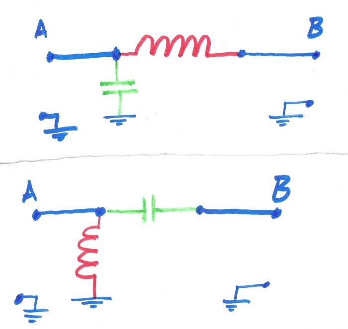
My antenna tuner uses an L-network. It has one adjustable capacitor and one adjustable inductor (coil of wire).  The inductor is in series with the signal (the signal passes through it) and the capacitor is situated between the signal line and the common/ground line. Because higher frequencies have a harder time getting through the inductor, you can tell that this is “low pass” configuration. If the inductor and capacitor traded roles it would be a “high pass” configuration. Generally, in a ham radio application it is better to use “low pass” so that higher harmonics of the operating frequency are discouraged from getting out onto the antenna and radiating to the rest of the world.
In this diagram, my L-network is like the top one.
There are two ways to connect it up. One way has the transceiver on the capacitor side of the inductor (A). The other way has the transceiver on other end of the inductor (B). The antenna takes the opposite end from where the transceiver attaches.
For impedence matching, if you hook it up one way it matches from high to low impedence. The other way matches from low to high impedence. So it works with antennas that are either higher or lower than what my transceiver desires to see.
The capacitor is a dual-gang air variable with a gearing system. I don’t know where it came from originally, my father gave it to me. The inductor/coil is a coil of wire that I made from regular house wiring wire. I used a PVC pipe form, wrapped the coil, and glued some nylon rope fibers to it with epoxy to keep it in shape. Then I soldered little wire tabs on every other turn. The idea came from an article in QST. I use an alligator clip to select the appropriate turn. I used these same parts plus one other coil on a parallel/ladder-line tuner in my previous radio shack. But in this situation my feedline is coax.
To find the right tuning I set up my transmitter on low output. Then I try various clip points with the alligator clip while I run the capacitor through it’s range., watching my SWR meter for a dip (matching condition). If I don’t find a useful spot I swap the transmitter and the antenna connections and go through it again.
In this picture my clip is bypassing the coil completely. The capacitor is at nearly-minimum capacitance. The yellow stuff is hot-melt glue.
