[today’s run: 5 miles]
Well, I’m glad I did the measurements yesterday but it turned out to be a bit of a wild goose chase. I was using the circuit layout for a low pass filter and the frequency response I measured was a low pass response. I was expecting to see a dip or a peak but my circuit wasn’t the right one for that kind of measurement.
Like all good hams, I then decided to read the directions. The EMRFD book, chapter 7, section 7.9 talks about how to measure the Q of a resonant LC circuit. And today I did that. And it worked just like they said it would. Amazing!
Here is the circuit I used today:
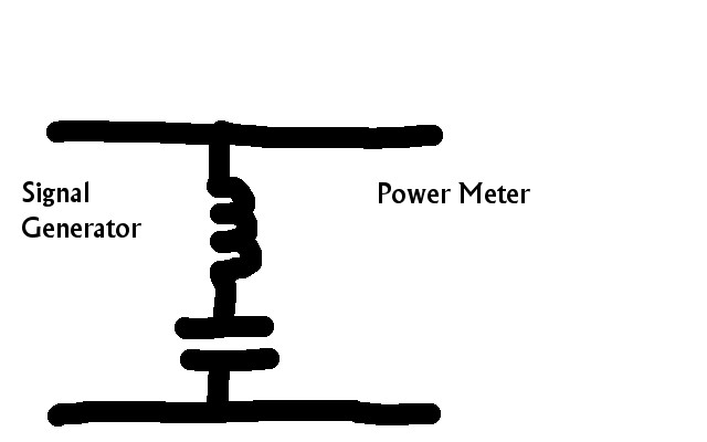
We have a 50 Ohm signal generator on the left, a 50 ohm power meter or spectrum analyzer on the right and our circuit elements in the middle in series. We tune for a null (dip) and record the minimum signal and the frequency at that point. Then I tuned to both sides of the dip to the point +3 dB from the null and record the frequency at those two points.
Since I was not too sure about my circuit elements yesterday I made up a pair today: two coils, one with copper wire and one with the Type A nichrome wire, each having 4 turns on FT37-62 ferrite toroid. Again I used the 470 pF mica capacitor in each case.
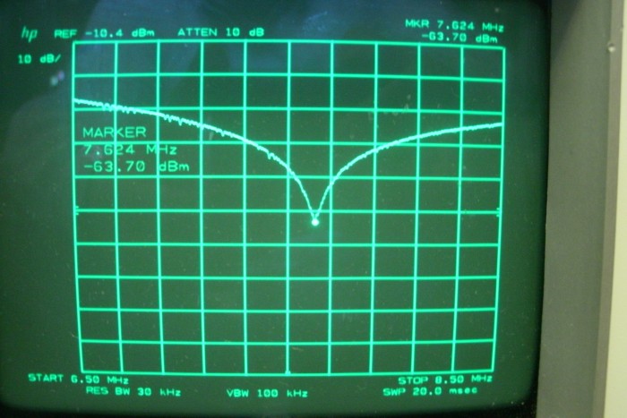
Here is the spectrum analyzer plot for the copper coil. I measured the null frequency at 7.62 MHz. The +3 dB frequencies were 7.64 and 7.61. I calculated the Q as 7.62/(7.64-7.61) = 254
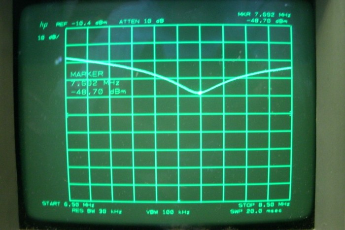
Here is the plot for the nichrome coil. I measured null at 7.61, +3 dB at 7.50 and 7.75. The resonance is the same as for the copper coil, within the margin of error for coil winding, but this time the Q is 30.4.
So my conclusion is that you can make resonant circuits with the high resistance wire but it lowers the Q by quite a bit. In this case the resistance of the NiCr coil was 1.8 Ohms and the Q was down by a factor of 8.
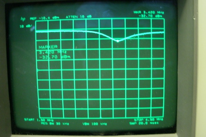
Here is the plot for yesterdays coil: 31 turns of nichrome type A wire on an FT50-6 toroid in series with the 470 pF capacitor. I measured the resistance of this coil at 11 Ohms and the Q is 9. Not very high. But it did give a definite null that I could measure.
One reply on “Nichrome Inductor – part 2”
I put the blog 12/20 into Google translate. It didn’t help. J/K
Happy holidays!