W6MSC AM Transmitter -- 13-Dec-2004 C. Howard
Update – September 26, 2005
Not much happened with the W6MSC transmitter
over the summer. Over the past weekend
I cleared out a bunch of stuff in the garage/radio-shack and finally started
thinking about it again. Yesterday I
put my SWR/Power meter between the output of the exciter deck and the input of
the final PA. It showed nothing…
completely dead. So I have some work to
do on the exciter deck. The first task
will be to replace the selenium rectifier installed on the back of the deck. Then I need to try to follow the signal path
through the exciter deck and see if I’m getting anything from the crystals on
forward. It will be a challenge to see
if I can get the exciter to work outside of the rack… I will need to examine
the interconnections and see if that can be done. While I’m on it, I need to create a true as-built schematic of
the exciter.
Update – May 12, 2005
I have the 250-TH tubes installed and all
tube filaments light up nicely. But I
am still having trouble getting the thing to go. When I power up the filaments come on, then there is a timed
delay. After the delay the green light
comes on. I push the ‘Start’ button and
I get activity in the rectifier tubes and I get some readings on the meters for
plate voltage. But red light also comes
on. When I release the ‘Start’ button,
it goes back to just having the filaments on.
So I suspect there is some kind of relay or
interlock that is not working right.
One mystery is the meaning of the term ‘NEMO’
which appears on some of the documents whose images are below.
Here are PDF file scans of some of the few
documents I received with this thing.
The documents are old and yellow, so they didn’t scan very well. If you have a specific question, let me know
and I will examine the originals.
On these power control schematics, I don’t
know how close they are to the actual construction. Everything checks ok so far, but I have not done a complete trace
of any of the power control decks.
main power
control deck | main
power deck - front panel
The first exciter page shows a schematic
somewhat different than the final construction. There is no 807 nor an
814. Instead there is a 832A followed by what looks like a 4E27A (the
label is completely gone). But the 6AG7
and 6V5 stages look similar to what was constructed.
exciter page
1 | exciter page 2 | exciter page 3
Update - March 12, 2005
I was able to locate the modulation
transformer from the original source. But no modulation or PA tubes were found.
Most of the interconnecting wires were labeled, as were the connections on the
rear of each deck. So I now have the wires connected and the connections
documented in a notebook. I also got the bias supply from the original source,
and some oil-filled capacitors and a large inductor ( 1 henry ) for the plate
supply filter. So as far as I can tell all of the hanging wires now have a home
and everything connects to something!
I spent quite a bit of time getting (temporary)
220V house power installed and a large power switchbox.
Current Condition
Right now I can fire up the filaments and
everything populated glows nicely. I am waiting on shipment of some 250TH PA
tubes. That should fill all the sockets. I was already able to gather up 4
working 813s for the modulator.. even though my advisors are telling me that 2
would do the job I'd like to start out with all the sockets filled. I also
acquired the 866 tubes for the auxillary plate rectifier circuit. The main
plate rectifier once had 872s but came to me modified with a large diode array.
I am hoping I can apply plate power after those 250th tubes are installed.
To Be Done
I need to rebuild a coil for the PA output
swinging link for use on 80 mtrs. I have half of the coil in good shape but the
other half is mangled. Coils for 40, 20 and 15(?) look ok.
Also need an external VFO to augment the
crystals that came with.
Audio system needs are unknown at this time.
I believe the modulator 813s need a relatively small amount of drive so I'm
going to start small and move up as needed.
Dec 13, 2004
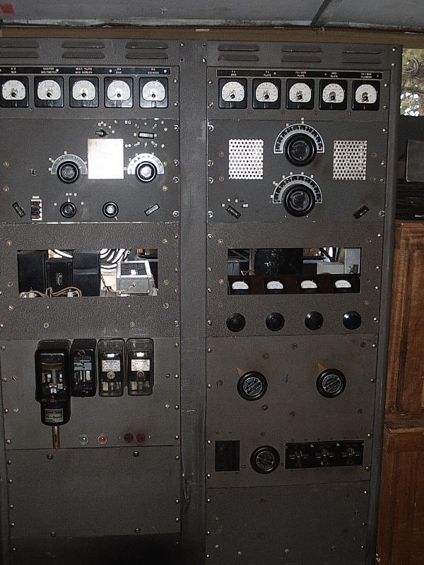
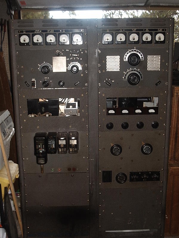
Here are some pictures of the W6MSC
transmitter with all of the decks mounted in the rack.
Here are a couple of shots of the front
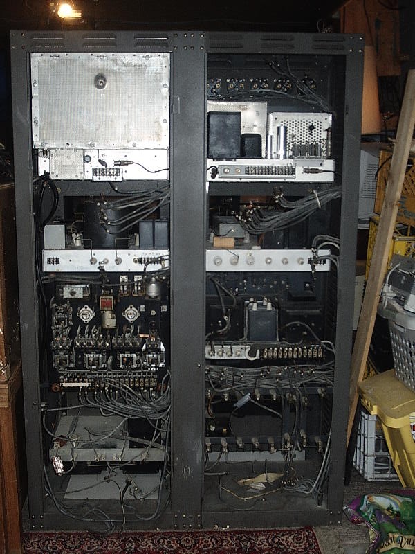
And a shot of the back
I have some closer shots of the front:
Front -
upper left -- meters and exciter
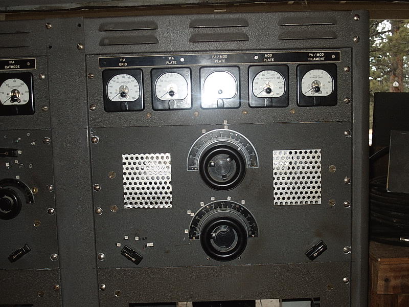
Front - upper right -- meters and power amplifier deck
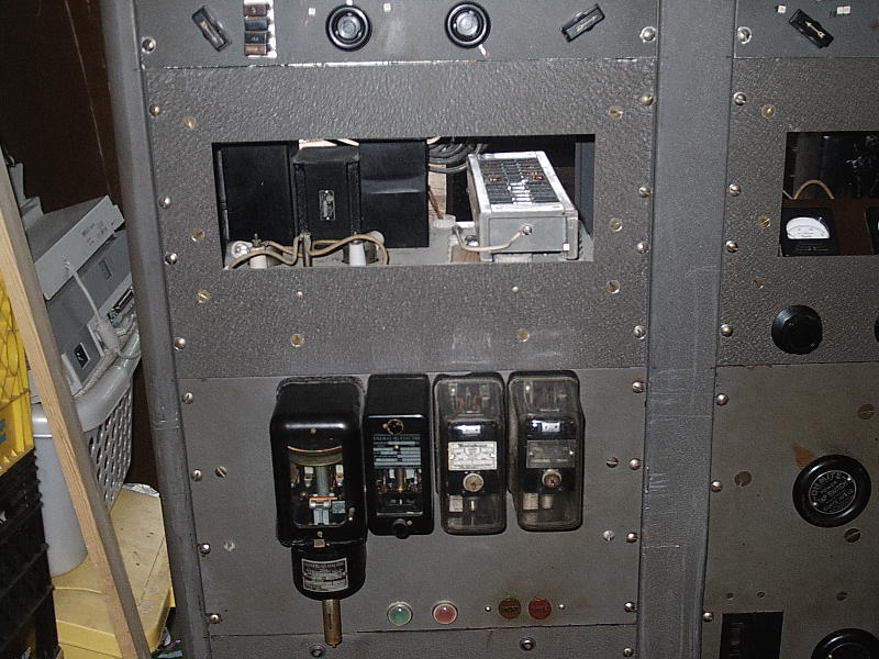
Front - middle left -- rectifier deck on top, power on bottom
Front - middle right -- modulation deck over power level controls
Front - lower -- power control
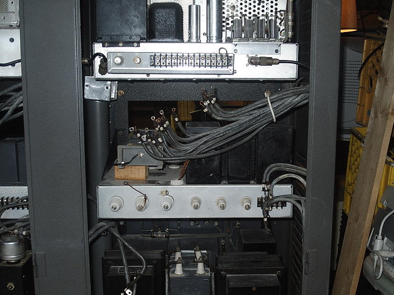
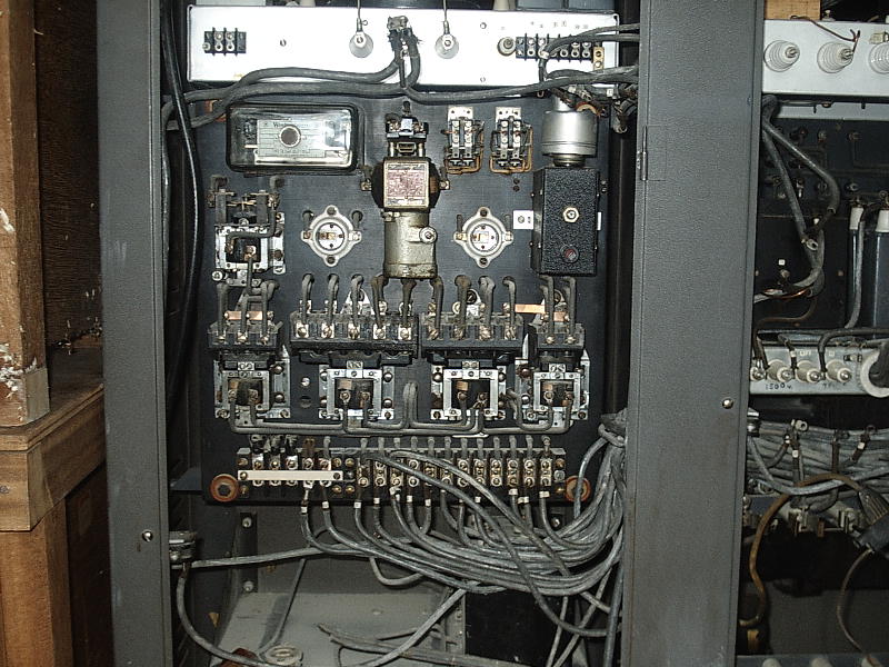
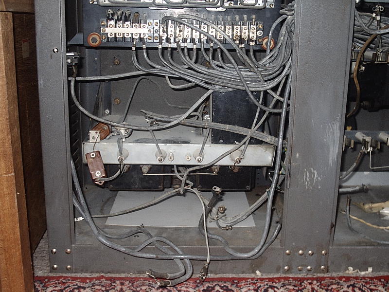
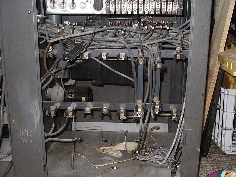
And closer shots of the back:
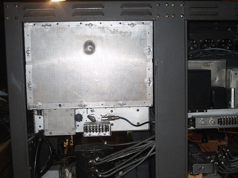
Back - upper left - power amplifier Back - upper right -- meters and exciter deck
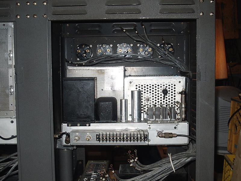
Back - middle left -- modulator Back - middle right -- rectifier deck
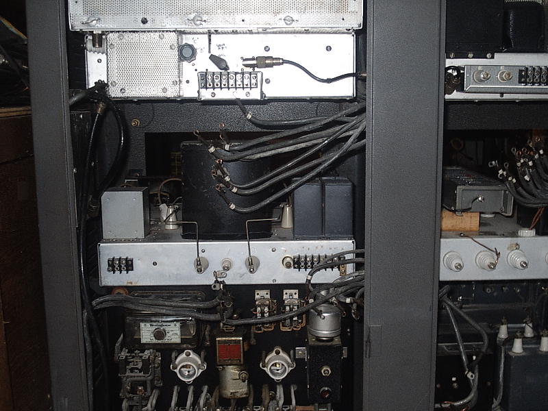
Back - lower left -- power control Back - lower right -- medium power deck
Back - bottom left -- mod xformer deck Back - bottom right -- plate xformer and space